T.L.E 30
Architectural Drafting
Tools for Manual Drafting
 A drafting table
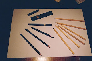
 Technical Pens and pencils used in drafting
.jpg)
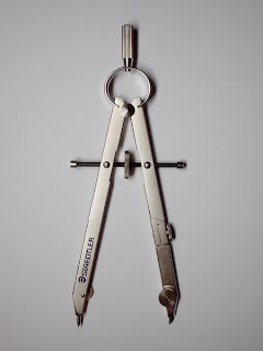
A bow compass
What is Manual Drafting?
Manual drafting is the way the engineering drawing are produced manually.
The basic drafting procedure is to place a piece of paper (or other material) on a smooth surface with right-angle corners and straight sides - typically a drafting table. A sliding straightedge known as a t-square is then placed on one of the sides, allowing it to be slid across the side of the table, and over the surface of the paper.
"Parallel lines" can be drawn simply by moving the t-square and running a pencil or technical pen along the t-square's edge, but more typically the t-square is used as a tool to hold other devices such as set squares or triangles. In this case the draftsman places one or more triangles of known angles on the t-square - which is itself at right angles to the edge of the table - and can then draw lines at any chosen angle to others on the page. Modern drafting tables (which have by now largely been replaced by CAD stations) come equipped with a parallel rule that is supported on both sides of the table to slide over a large piece of paper. Because it is secured on both sides, lines drawn along the edge are guaranteed to be parallel.
In addition, the draftsperson uses several tools to draw curves and circles. Primary among these are the compasses, used for drawing simple arcs and circles, and the French curve, typically a piece of plastic with complex curves on it. A spline is a rubber coated articulated metal that can be manually bent to most curves.
Drafting templates assist the draftsperson consistently recreate recurring objects in a drawing without having to reproduce the object from scratch every time. This is especially useful when using common symbols; i.e. in the context of stagecraft, a lighting designer will typically draw from the USITT standard library of lighting fixture symbols to indicate the position of a common fixture across multiple positions. Templates are sold commercially by a number of vendors, usually customized to a specific task, but it is also not uncommon for a draftsperson to create their own templates.
This basic drafting system requires an accurate table and constant attention to the positioning of the tools. A common error is to allow the triangles to push the top of the t-square down slightly, thereby throwing off all angles. Even tasks as simple as drawing two angled lines meeting at a point require a number of moves of the t-square and triangles, and in general drafting can be a time consuming process.
A solution to these problems was the introduction of the mechanical "drafting machine", an application of the pantograph (sometimes referred to incorrectly as a "pentagraph" in these situations) which allowed the draftsman to have an accurate right angle at any point on the page quite quickly. These machines often included the ability to change the angle, thereby removing the need for the triangles as well.
In addition to the mastery of the mechanics of drawing lines, arcs and circles (and text) onto a piece of paper - with respect to the detailing of physical objects - the drafting effort requires a thorough understanding of geometry, trigonometry and spatial comprehension, and in all cases demands precision and accuracy, and attention to detail of high order.
Although drafting is sometimes accomplished by a project engineer, architect - or even by shop personnel such as a machinist - skilled drafters (and/or designers) usually accomplish the task and are always in demand to some level.
The required sizes of features are conveyed through use of dimensions. Distances may be indicated with either of two standardized forms of dimension: linear and ordinate.
- With linear dimensions, two parallel lines, called "extension lines," spaced at the distance between two features, are shown at each of the features. A line perpendicular to the extension lines, called a "dimension line," with arrows at its endpoints, is shown between, and terminating at, the extension lines. The distance is indicated numerically at the midpoint of the dimension line, either adjacent to it, or in a gap provided for it.
- With ordinate dimensions, one horizontal and one vertical extension line establish an origin for the entire view. The origin is identified with zeroes placed at the ends of these extension lines. Distances along the x- and y-axes to other features are specified using other extension lines, with the distances indicated numerically at their ends.
Sizes of circular features are indicated using either diametral or radial dimensions. Radial dimensions use an "R" followed by the value for the radius; Diametral dimensions use a circle with forward-leaning diagonal line through it, called the diameter symbol, followed by the value for the diameter. A radially-aligned line with arrowhead pointing to the circular feature, called a leader, is used in conjunction with both diametral and radial dimensions. All types of dimensions are typically composed of two parts: the nominal value, which is the "ideal" size of the feature, and the tolerance, which specifies the amount that the value may vary above and below the nominal.
- Geometric Dimensioning and Tolerancing is a method of specifying the functional geometry of an object.
Multiple views and projections
In most cases, a single view is not sufficient to show all necessary features, and several views are used. Types of views include the following:
- orthographic projection - show the object as it looks from the front, right, left, top, bottom, or back, and are typically positioned relative to each other according to the rules of either first-angle or third-angle projection. The former is primarily used in Europe and Asia, the latter is primarily used in the United States and Canada. Not all views are necessarily used, and determination of what surface constitutes the "front," etc., varies from object to object. "Orthographic" comes from the Greek for "straight writing (or drawing)."
- section - depict what the object would look like if it were cut perfectly along cutting plane lines defined in a particular view, and rotated 90° to directly view the resulting surface(s), which are indicated with section lines. They show features not externally visible, or not clearly visible.
- detail - show portions of other views, "magnified" for clarity.
- auxiliary projection - similar to orthographic projections, however the directions of viewing are other than those for orthographic projections.
- isometric- show the object from angles in which the scales along each axis of the object are equal. It corresponds to rotation of the object by ± 45° about the vertical axis, followed by rotation of approximately ± 35.264° [= arcsin(tan(30°))] about the horizontal axis starting from an orthographic projection view. "Isometric" comes from the Greek for "same measure."
- Geometry – the shape of the object; represented as views; how the object will look when it is viewed from various standard directions, such as front, top, side, etc.
- Dimensions – the size of the object is captured in accepted units.
- Tolerances – the allowable variations for each dimension.
- Material – represents what the item is made of.
- Finish – specifies the surface quality of the item, functional or cosmetic. For example, a mass-marketed product usually requires a much higher surface quality than, say, a component that goes inside industrial machinery.
A variety of line styles graphically represent physical objects. Types of lines include the following:
- visible – are continuous lines used to depict edges directly visible from a particular angle.
- hidden – are short-dashed lines that may be used to represent edges that are not directly visible.
- center – are alternately long- and short-dashed lines that may be used to represent the axes of circular features.
- cutting plane – are thin, medium-dashed lines, or thick alternately long- and double short-dashed that may be used to define sections for section views.
- section – are thin lines in a pattern (pattern determined by the material being "cut" or "sectioned") used to indicate surfaces in section views resulting from "cutting." Section lines are commonly referred to as "cross-hatching."


0 comments:
Post a Comment